Chapter 3 Insulation
3.1 Technical data
The key building characteristics are listed below. What this table does not reflect is the attention to detail that is required when installing insulation (i.e. ensuring complete coverage and no compression) and minimisation of thermal bridges.
| Internal volume | 495 m3 |
| Airtightness | |
| Air changes per hour @ 50 Pa (ACH50) | 1.2 |
| Mechanical ventilation and heat recovery (MVHR) | Zehnder Comfoair 550 |
| Insulation | |
| Ceiling | R8.0 |
| Suspended floor | R2.9 |
| Rammed earth wall | R4.0 |
| Timber framed walls | R4.2 |
| Glass | R1.4 (U0.7) |
3.2 Insulation
Conventional glasswool insulation batts were used underfloor, in the ceiling and walls. Higher density batts were chosen as they (a) have additional stiffness such that they are less likely to sag over time, and (b) provide marginal additional sound absorbing properties. Extra care was used in placing the batts to ensure there were no gaps and that the batts were not unduly compressed. Recall that the performance of insulation is not due to the material itself but rather the capture of many small air pockets within the material. If a batt is compressed there will be far fewer air pockets and hence lower insulation values, so it is vitally important that the batts be installed with great care.
Figure 2: Typical wall insulation - this is the second layer inside airtightness membrane, studs are offset from outer wall
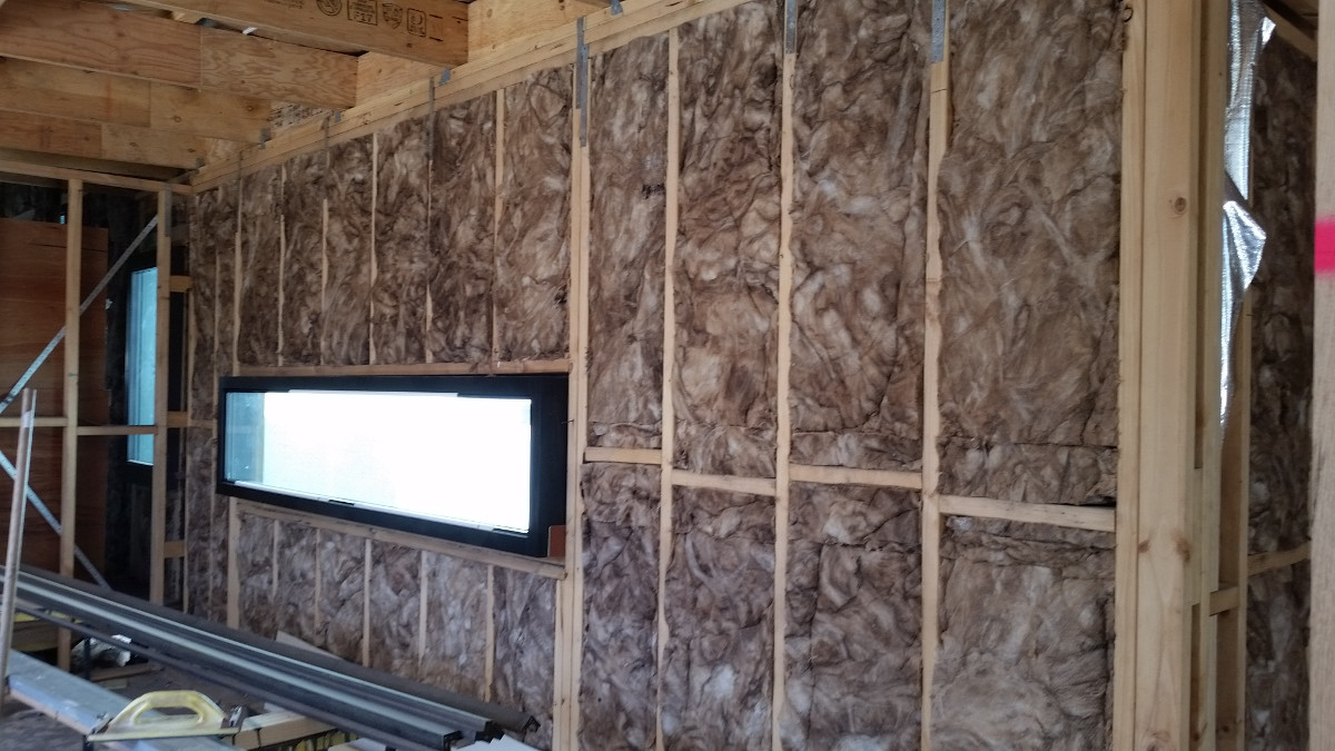
A conventional timber stud wall construction is 90 mm thick. This provides inadequate depth to achieve the levels of insulation we required - the batt itself has an R-value of around 2.5 but recall that around 15% of the wall area is timber studwork (which has R0.8 for 90 mm wide pine) so the effective R-value will be less than R2.0. In the older part of the home we installed an additional 90 mm stud wall internally and placed the airtightness membrane between these walls. Each wall was filled with high density R2.7/90 mm batts. This construction provides an R-value of around R4.2 (accounting for the presence of the timber framing). In the new extension the double-stud construction was also used.
By placing the airtightness membrane in the middle of the wall thickness we risk condensation forming on the inner membrane face in winter. While the modelling suggests this risk is minimal it would be better practice to place the membrane towards the inner (warm) side of the wall construction and then provide a small (around 20 mm) services cavity between the membrane and plasterboard. However, one notional advantage of the method we have used is that the membrane is 100 mm behind the inner face of the plasterboard, ensuring we’re unlikely to accidentally pierce it in the future.
3.2.1 Windwashing
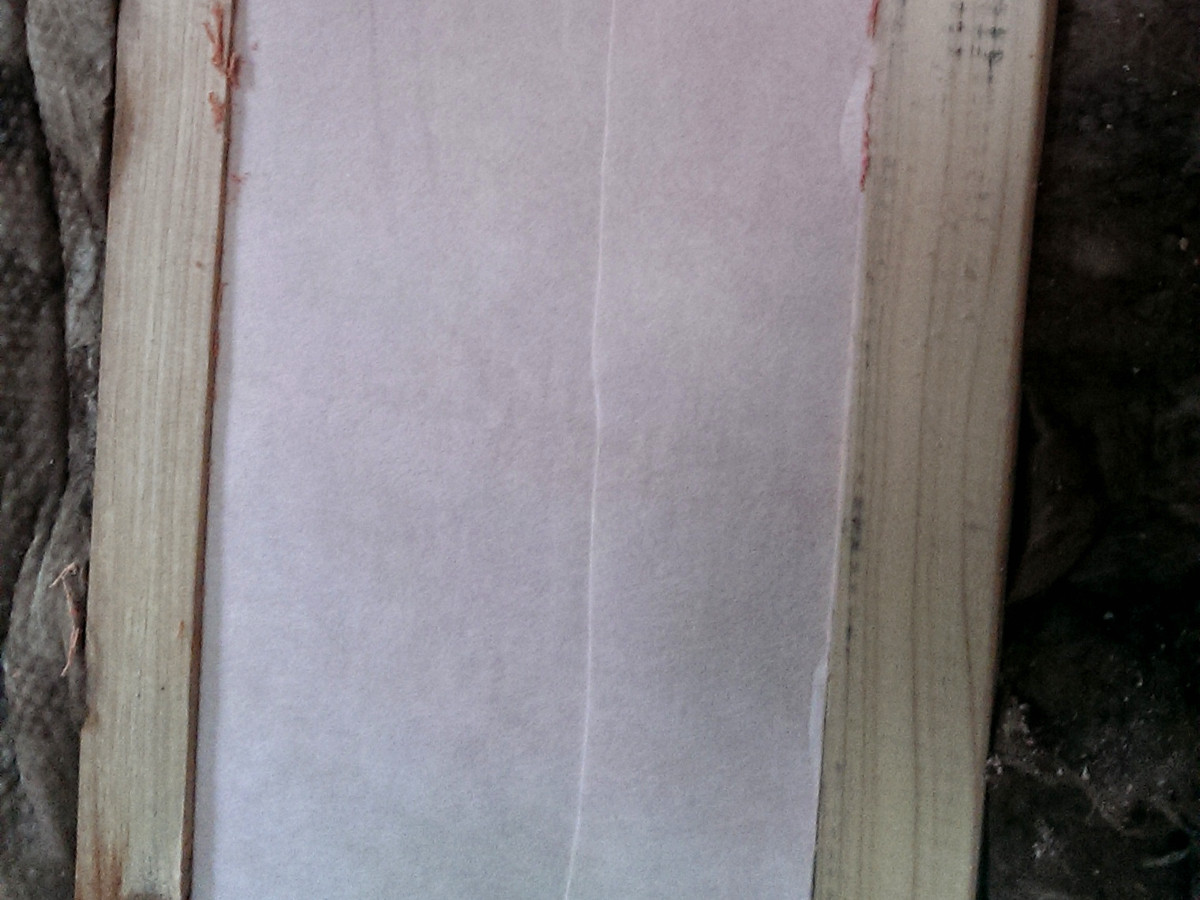
Imagine walking outside on a cold winters day with only a fleece or woollen jumper. As long as it is not windy this may well be sufficient to ensure you keep warm. However, if it were also windy you would likely feel the cold air penetrating right through the jumper. To solve this problem we often wear a thin windproof jacket on top. In other words, we have a bulk insulator (the jumper) protected from the wind by a membrane (the jacket). The same principle applies to bulk insulation in buildings; to achieve the greatest insulation performance it is necessary to wrap the insulation. This is commonly done, albeit poorly, using aluminium foils. The motivation for these weatherwraps is normally to ensure water cannot penetrate into the wall construction from outside. As long as this layer is taped along the joins it can serve to eliminate the wind washing. However, almost all aluminium weatherwraps have low vapour permeability. This means that in winter any vapour entering the wall from inside (say, from along the skirting board or wherever there are penetrations such as powerpoints) cannot escape to the outside and instead there is a risk of condensation forming in the wall cavity behind the weatherwrap. For this reason it is important to specify a vapour open (“breathable”) membrane such as Pro Clima Solitex, Siga Majvest or Bradford ProctorWrap.
3.3 Thermal bridging
A thermal bridge occurs in a construction where there are multiple materials of differing thermal conductivity such that heat can readily escape (or enter) through the material with the highest conductivity. When building for efficiency this becomes increasingly important. Around 15% of a typical timber wall construction will be timber framing. Timber has a thermal conductivity around three times greater than standard glasswool insulation, so a wall with R2.5 batts will perform closer to R2.0, as noted above.
Figure 3: Thermal conductivity of typical materials
By far the best thermal conductor in typical home construction is steel. We tried to minimise the use of steel, but where it absolutely was required (the spine of the butterfly roof and as supports for the chimneys) we used phenolic foam sheets to try and keep the steel on the cool (outer) side of the insulation. The other issue we’d point to here is the widespread use of aluminium for window and door frames. These are excellent thermal highways and must be avoided in any efficient building design.
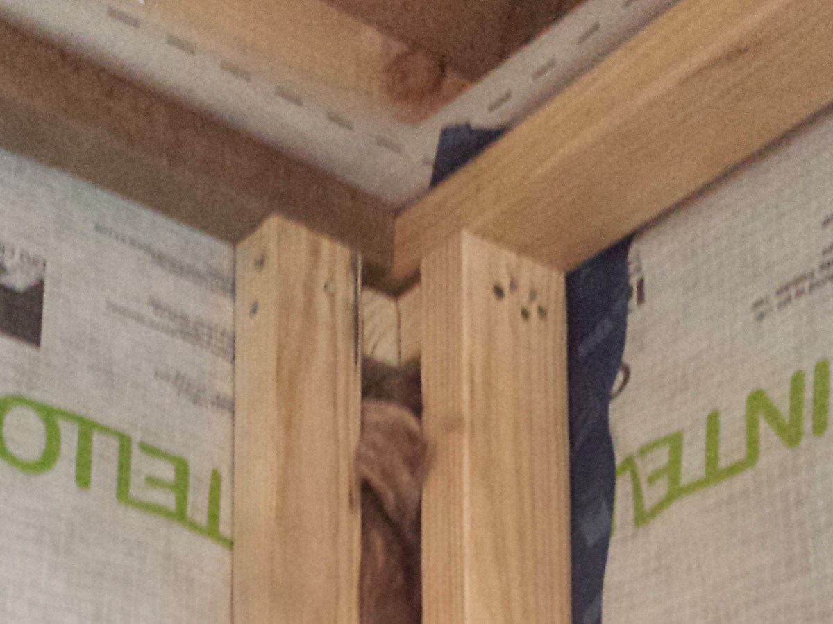
Figure 4: Thermal bridging detailing
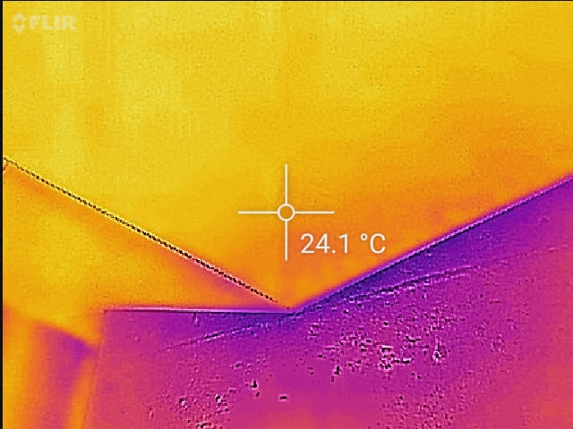
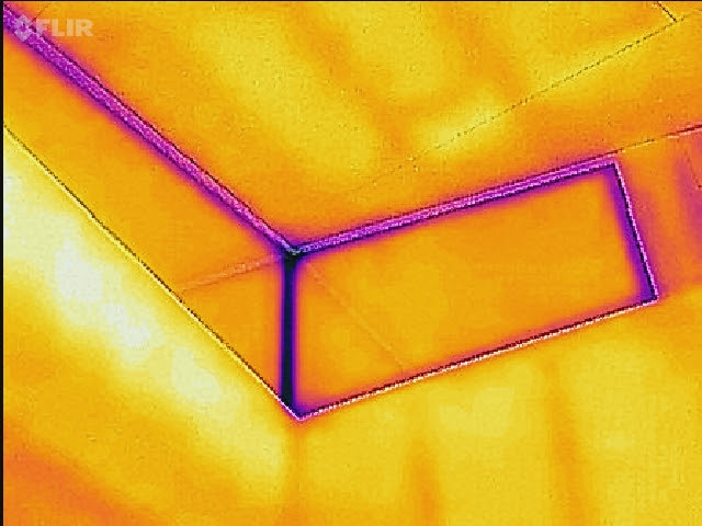
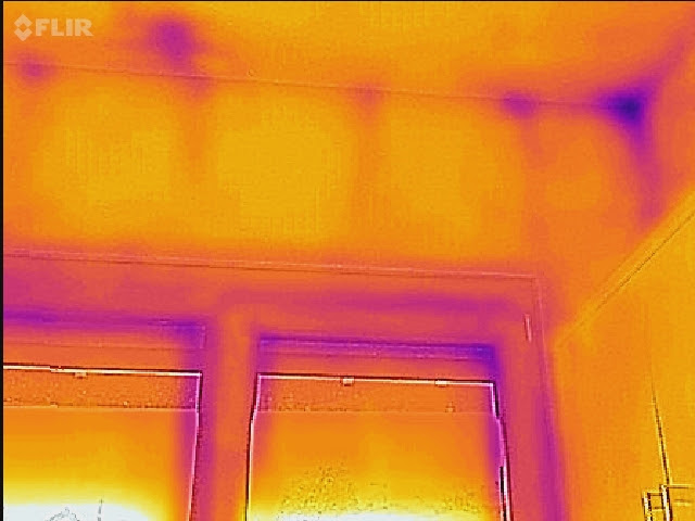
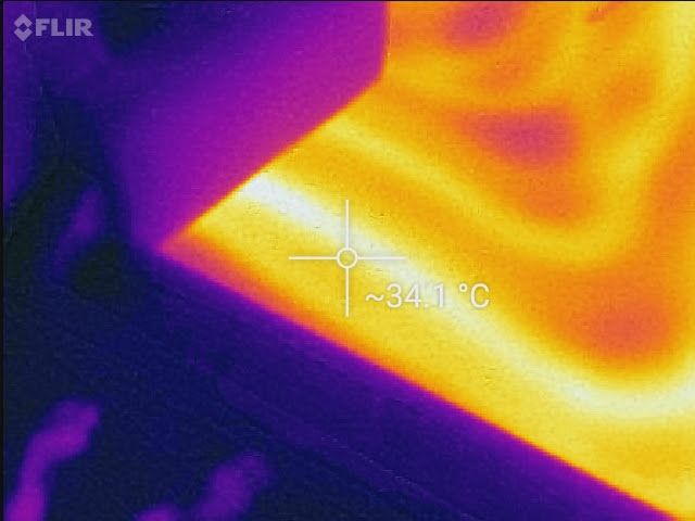
3.4 Thermal imaging
We found thermal imaging very useful to identify weaknesses in the insulation installation, particularly around corners where it was not evident to the naked eye the insulation was incomplete. Examples are shown below.